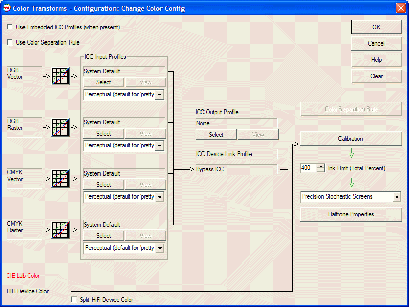
Illustration 1: Clearing the Color Transforms menu
| HOT KEYS (SHORT CUTS) RELATED TO THE COLOR CALIBRATION WINDOW | |||||||||||||||||||||||||||||||||||||||||||||||||||||
|
|
||||||||||||||||||||||||||||||||||||||||||||||||||||
This document focuses mainly on peforming calibrations with CMYK inks (or CMYK with dilute inks); procedures for linearizing 5 or more colorants (such as Orange and Green) will differ slightly.
Color calibration is the process of linearizing the printer and print scenario. It is typically done with a densitometer or colorimeter and involves two steps.
Individual ICC profiles can be adapted to changes in media or humidity (which may cause dot gain or dot loss) by performing the calibration step again.
In Imaging Configurations distributed by Wasatch, calibration is performed before producing an ICC profile. Therefore, our internal ICC profiling process sees a virtual linear device, not a highly variable physical device.
In the Imaging Configurations screen, select the Properties for the printer to be calibrated. Make all settings on the Properties window before proceeding with Calibration. All printer settings, inks, media, print modes, etc. must be selected prior to calibration.
Click the Clear button on the Color Transforms screen (Illustration 1).

Illustration 1: Clearing the Color Transforms menu
Open and print one of the "generalTestXXX.ps" files, which are located in the "psfiles" folder on your harddrive. This folder was installed automatically when you installed SoftRIP.
This test pattern (Illustration 2) will help you establish if ink reductions or total ink limits are required, and may include a test pattern specific to your measurement device. Note that there are several versions of this file, each pertaining to an individual measurement device (densitometer). If you have a device that matches one of these "generalTest.ps" files, it will be convenient for you to print the matching file.
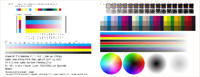
Illustration 2: generalTest.ps image
In the Color Transforms window, click on the Calibration button. This launches the "Calibration" window (Illustration 3).
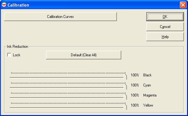
Illustration 3: Calibration window
Note the "Ink Reduction" slider bars at the bottom of this window. If you determine that you require individual ink channel reductions, use these sliders to reduce ink appropriately. If you perform ink reductions, it is extremely important that you save the imaging configuration and reprint any test patterns you have printed thus far prior to measuring any calibration data.
If you are using a print mode that has a fixed dot size and uses dilute inks (such as Light Magenta, Light Cyan, and/or Light Black) with the Precision Stochastic Screens halftone, YOU MUST NOT perform your ink reductions on this window.
Instead, click on the "Halftone Properties" button below the selection for Precision Stochastic Screens on the "Color Transforms" window (Illustration 4). Click the "Fixed Dot Ink Reduction" checkbox, and then perform your ink reductions here.
You will NOT measure any data into this window. Once you have completed your ink reductions, save the imaging configuration, re-print your test patterns, and return to the standard "Calibration" window (NOT the "Halftone Properties" window) to proceed.
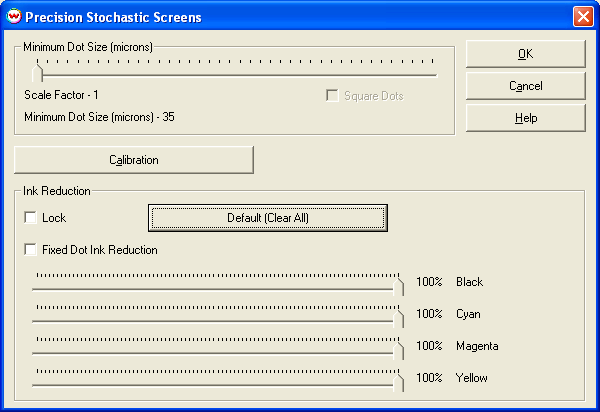
Illustration 4: Halftone Properties Ink Reduction window
Now is also a good time to determine your "Total Ink Limit" (located on the "Color Transforms" window), if necessary. This can be done using the "generalTest.ps" file's upper-right color swatches, which consist of areas of ink ranging from 0% ink through 400% ink.
If your measurement device does not match any of the "generalTest.ps" files, you will now need to print the appropriate test pattern for your densitometer before proceeding (illustration 5). These test patterns are also located in the "psfiles" folder.

Illustration 5: Example linearization pattern (dtp41.ps)
After you have determined appropriate ink reductions and re-printed your test patterns (or determined ink reductions were not necessary), click the "Calibration Curves" button. This will launch the window in which you will measure your calibration data (illustration 6).
There are two options provided for calculating the curves required to make the printer print "linearly". You can calculate with respect to "density" or with respect to "dot area". Use the "Options" menu on this window to choose between performing a density linearization (default) and a dot area linearization. Your choice should be driven by your output type and more importantly by the expectations of your ICC profiling software. You may need to test each setting to determine which provides best results with your profiling package.
Once you have determined the type of calibration you want to perform, click the "Densitometers" menu to select a color measurement instrument. Most SoftRIP-supported densitometers provide a Wizard to guide you through Calibration and input of data from your test pattern. More information on specific instrument brands is found in the "Densitometers" area of online help.
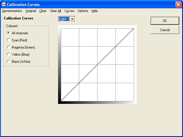
Illustration 6: Calibration Curves window
Once densitometric data has been entered, Calibration Curves will be displayed on the main window of the Calibration screen. If your device is nearly "linear", the curves will be fairly close to straight lines; more likely, you'll see substantial curvature. These curves are not the data you measured. They are the curves computed by Wasatch SoftRIP to cause the printer to print linearly.
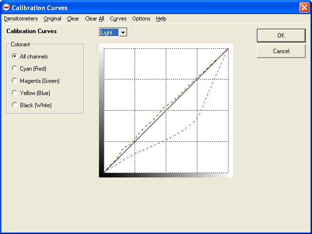
Illustration 7: Example of Calibration Curves
| Recall Original Data: The Original button allows for viewing and editing previously entered densitometric data. This button launches a screen displaying original measurements for each channel, which can be changed and saved. |
Click OK to exit the Calibration Curves and Calibration screens. Make sure to save the Color Transforms window, and make sure, as well, to save your work into an existing or new imaging configuration when prompted.
Using these calibration curves, you can create a custom ICC profile using any 3rd party profiling software package and import it into SoftRIP's "Color Transforms" window. Building your own profiles on top of a linearization provides a powerful method to control your imaging configurations in the event of environmental changes that could potentially lead to changes in your output.