WASATCH SOFTRIP
Profiling with Error Diffusion
Revised September 12, 2024
Getting Started
Color measurement instruments and profiling software have become commonplace, available from places like Amazon. The issue for users of these products is that their correct use is different for different printing systems, and RIP software.
This document outlines the steps to create ICC profiles using a combination of Wasatch SoftRIP and a third party color profiling software package, such as X-Rite i1Profiler. The combination of an imported ICC profile and settings saved within Wasatch SoftRIP will be referred to as an "Imaging Configuration". It will also cover processes for Hi-Fi profiling and collecting, and installing Imaging Configurations at a remote site.
In addition to this document, you will also need to refer to the ICC profiling software manual for intermediate steps where noted. It is recommended that a minimum of 30 linear feet of media be allocated to produce each Imaging Configuration.
CONTENTS:
On the Print Setup window, click the Edit button. This will launch the Imaging Configuration window.
Click the Properties button. This will open a window that has additional settings for the printer, such as print modes, resolutions, inksets, etc. Every printer has a different set of properties. Determine the intended output configuration and select from features included with the printer. When the selections are complete, click OK.
NOTE: It is extremely important that all printer settings, halftone settings, inks, media, print modes, and other factors that affect the print condition be set prior to ink limiting. If these settings are changed, you must return to the beginning of Step 1 to restart the process.
On the Imaging Configuration window, click the Edit Info button and create a text file to record the properties selected as part of the configuration. This is especially helpful if the final Imaging Configuration will be distributed, and is a good place to keep track of changes as the Imaging Configuration is built. When Edit Info is clicked, the computer's default text editor will open for entering notes. When done, select Save from the File menu and the information will be saved within the Imaging Configuration, but this file can be edited at any time. And this information will be available to anyone who clicks the Info button later. Once the file is saved, click OK to return to the Print Setup window.
STEP 2: COLOR TRANSFORMS CONFIGURATION
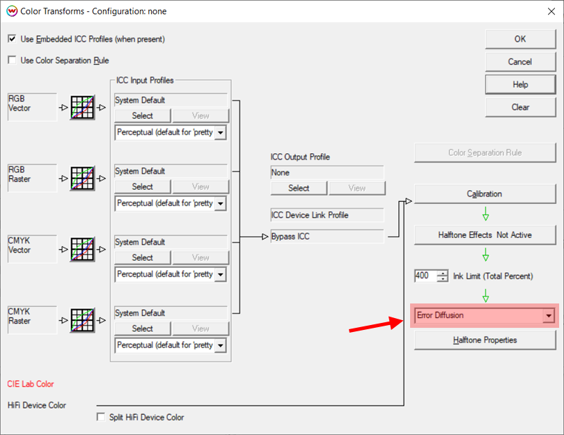
From the Imaging Configurations window, click on the Color Transforms button to launch the Color Transforms window. This is the master color flowchart window. Notice that the controls are set to default with the color data cleared, as a result of setting the Imaging Configuration to none. In the lower right of the window, change from Precision Stochastic Screens to Error Diffusion. This is a higher quality screening process than our Precision Stochastic Screens, since it is free of any periodic patterning, but will increase the processing time of the image rasterization (ripping).
In the ICC Input Profile column on the left side of this window, the four input color spaces (RGB Raster, RGB Vector, CMYK Raster, and CMYK Vector) should all be set to System Default. Also, the default rendering intent of Perceptual has been set. If the design workflow includes using embedded ICC profiles, check the Use Embedded ICC Profiles box.
Click OK to exit the Color Transforms window and click OK again to exit the Imaging Configuration window. A Save As window will open allowing you to name the new Imaging Configuration. We recommend naming the "in-progress" Imaging Configuration with a name like Unlinearized_None. If making an Imaging Configuration for use in a production capacity, it may be best to avoid too many ambiguously named Imaging Configurations by using a more detailed naming system such as: Unlinearized_None_resolution_inktype_media.
STEP 3: TEST PRINT
On the Print Setup window, make any other non-color related selections required for printing. These settings include Physical Connection, Paper Width, Margins, Mirroring, and Crop Marks. Once set, click OK. SoftRIP is now ready to print the test prints.
If you are creating a profile as part of the Wasatch Color Profiling Assessment program, you should print a Self Documenting Test File now. This print should be sent to the Wasatch Computer Technology office at the end of the profiling process.
Otherwise, from the File menu, select Open and browse to C:\psfiles then select the appropriate target file for the densitometer being used (such as generalTest018eyeone.ps). With the file open, select RIP and Print to print the file. The resulting print will be evaluated in the next section.
NOTE: The exact location of the psfiles folder may vary depending on the drive to which SoftRIP was installed.
STEP 4: DETERMINE INK LIMITING
To begin evaluating the print, first determine if an Individual Channel Ink Reduction is needed on one or more of the individual channels. An Individual Channel Ink Reduction is intended to set the maximum amount of ink that will be needed, or that the media can retain.
Ink reduction is performed for each channel, so look at the patches for each color individually. Examine each color channel contained in the linearization target in the top left of the generalTest print. If any visible over-inking artifacts are present, such as undried ink, bleeding, substrate warping, etc., an ink reduction should be applied to that specific channel.
To make adjustments to the Individual Ink Channels, and if a Variable Dot Type was selected on the Properties window, click the Calibration button from the Color Transforms window and use these slider controls to set the ink reductions. These controls may be used for any channel individually or for all channels together if the Lock box is checked.
NOTE: Steps differ if a Fixed Dot Type was previously selected on the Properties window.
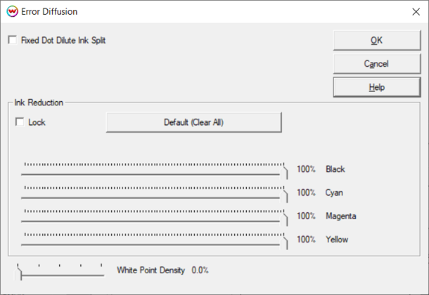
When using a printer that only prints in a fixed dot mode, or a fixed dot mode was chosen on the Properties window, then the individual ink reductions should be made in the Error Diffusion window instead of the Calibration window. Click the Halftone Properties button below the Error Diffusion selection to open the window.
NOTE: Never use both sets of Individual Ink Channel Reduction controls at the same time.
If printing with dilute inks (light cyan, light magenta, light black, gray, light gray, etc.) and the printer is in a fixed dot mode, check the Fixed Dot Dilute Ink Split control.
Total Ink Limit: Refer to the printout of the generalTest file to determine if a Total Ink Limit is needed, in addition to the Individual Ink Channel Reductions. The upper right area of the test print consists of three parts. The first part is a step pattern from 0% to 400% total ink. For the Total Ink Limit, select the highest percentage square that is dry and does not have print artifacts.
The third part is a series of three rows of swatches located below the boxes of black lines. These swatches consist of primary inks and one CMY black in the upper right corner (circled in red). The CMY black may show excessive bleeding or artifacts due to the “inks mixing” where the first two tests above do not. This is why it’s very important to review this patch. Check this area for individual ink channel retention issues.
Be aware of the amount of drying time needed before the patches can be handled in this step because this may indicate that further ink limiting is required. This is an individual preference and is determined by what drying time would be acceptable in a production environment.
If there are issues with any of these test patterns, set a Total Ink Limit or return to the Individual Ink Channel Reduction step to apply stronger reductions. If setting a Total Ink Limit in Wasatch, return to the Color Transforms window. Above the Halftone Properties on the right side of the Color Transforms windows is the Ink Limit (Total Percent) control. Enter the percent for Total Ink Limit, click OK to exit the Color Transforms window, click OK to exit the Imaging Configuration window, and save the “unlinearized” Imaging Configuration.
IMPORTANT NOTE: Wasatch noticed improved results when the Total Ink Limit was applied within the profiling software rather than within SoftRIP. After determining the Total Ink Limit using the method described above it is recommended to use this value when generating the patches in the profiling software, not in SoftRIP. The total ink limit will be handled by the ICC profile, which allows a smoother transition from all colors to black than using the control in SoftRIP.
If the media requires a Total Ink Limit to be set in SoftRIP to limit excessive bleeding then please do so now. During Step 8 when generating the ICC patches please reset the Total Ink Limit control in SoftRIP back to the maximum value and then set the limit using the ICC software controls. Please refer to the profiling software documentation for how to set a Total Ink Limit when generating patches.
STEP 5: TEST PRINT
If you are creating a profile as part of the Wasatch Color Profiling Assessment program, you should print a Self Documenting Test File now. This print should be sent to Wasatch Computer at the end of the process.
Otherwise RIP and print the generalTest file to check for any additional Individual Channel Ink Reductions or Total Ink Limits that may be required. All squares should have good retention, show no print artifacts, and have no bleeding problems. If there are still ink retention issues, depending on the printer model, there are other options that can be used for limiting ink. For example, lower the resolution or change to a dry mode (if available). If changes to these settings are required to create a quality Imaging Configuration, restart the profiling process from Step 1.
STEP 6: LINEARIZE (CALIBRATE) THE PRINTER
Open generalTest018eyeone.ps, eyeone.ps, or an appropriate linearization file that matches your scanning device. Use the generalTest018eyeone.ps file if performing the profile assessment. Find more information on which file to use for the spectrophotometer in the Densitometers section of SoftRIP's online help.
RIP and print the selected linearization test pattern.
Return to the Color Transforms window and click the Calibration button, then click the Calibration Curves button to launch the Calibration Curves window.
Use the Options menu on this window to choose between density linearization (default) and a dot linearization. The choice should be driven by the output type and, more importantly, by the expectations of the ICC profiling software. Test each setting to determine which provides the best results with the profiling package.
Select the densitometry hardware from the Densitometers menu. Device-specific instructions for reading the linearization patches will be displayed. After following the on-screen instructions and reading the test patterns/strips, click OK to exit.
The resulting data will be displayed in the Calibration Curves window and will look similar to the curves shown here. If measuring a smooth substrate without any surface texture, the appearance of the curves will usually be smooth without any abrupt shifts in the direction of the curve. If such discontinuities exist, this may indicate the presence of an inaccurate measurement. See steps below to help verify the resulting linearization curves.
Choosing Original from the top menu, on the Calibration Curves window, will display the density measurements for each patch on the linearization target. By reviewing these values, over-inking issues that may not be visible to the naked eye on the print can be found. For each color, the highest measured density should be displayed at the top of the column with each value below showing a lower measured density. If a higher value is displayed below a lower value, as shown in the image with the Cyan channel, this indicates that too much ink is being printed for that color channel, even if the scanned print had no visual over-inking artifacts.
As ink increases, the measured density will also increase, but only to a certain point. As the printed ink amount increases and the maximum achievable density measurement is approached, the increase in density diminishes and eventually drops off completely. Once this point is reached, printing more ink will often result in the measured density value being lower.
To address this issue, cancel out of the Calibration Curves window without saving the linearization curve, perform an Individual Channel Ink Reduction to the channel(s) with this over-inking issue, resave the Imaging Configuration, RIP and print the test target, and re-measure. Repeat these steps as necessary until the maximum measured density is displayed at the top of the column in Original Data for each color, with all values below descending.
When complete, click OK until the Save As window is displayed. Name the Imaging Configuration so that it is identified as the original linearization data.
NOTE: Exit all windows by clicking OK, instead of Cancel, or the data will be lost.
STEP 7: CONFIRM LINEARIZATION (Optional)
NOTE: This step is optional and not necessary to create an Imaging Configuration. However, as this step will help confirm the accuracy of the linearization curve scanned into SoftRIP in Step 6, and an accurate linearization curve is an important part of a quality Imaging Configuration, it is highly recommended to follow the instructions below closely to confirm the linearization process was successful.
NOTE: As this step is only to confirm that the linearization curve is accurate, DO NOT use the OK button when exiting from these windows during this step unless explicitly instructed to do so. It is very important to use the CANCEL button to exit all windows. Clicking OK will write over the linearization data with the confirmation data and invalidate the curve data.
RIP and print the same linearization test pattern from Step 6 using the linearized Imaging Configuration (with saved curves). If one of the generalTest files was used, RIP and print it again.
Open the Calibration Curves window. Use the Options menu to select the same linearization type used in the original linearization. Select the hardware from the Densitometers menu again and follow the steps to read the linearization patches from this newly printed target.
When asked to overwrite or add the new curves to the linearization, choose Yes.
Now the curves shown in the Calibration Curves display should look nearly linear (straight along the diagonal line). If the curves look linear, use the Cancel button to back out of all windows and return to the main window.
If the curves do not look linear, have large bumps, or fall sharply away from the center line, perform a new linearization. To do this, first clear out the linearization curves by using Clear All from the top menu. Click OK to exit out of the Calibration, Color Transforms, and Imaging Configuration windows. Resave the Imaging Configuration with a new name (such as Linearization_Second_Attempt).
Return to Step 6 to perform a new linearization and repeat the steps to confirm linearization. If the curves still have bumps or fall away from the center line after the second confirmation, reconsider the Individual Channel Ink Reduction settings. It is recommended to speak with a Wasatch technician for assistance.
STEP 8: PRINT PROFILE TARGET
If you are completing the Wasatch Color Profiling Assessment program you should print a Self Documenting Test File now. This print should be sent to us at the end of the process. Then move on to print the profiling target which you should also send.
The profiling software being used will provide a standard set of patches that will need to be printed through SoftRIP and read with the spectrophotometer. Use the controls available in this software to generate a target with the appropriate Total Ink Limit as determined in Step 4 above. If a Total Ink Limit was temporarily set in SoftRIP during Step 4 please reset the control back to the maximum value now.
Open the file generated by the profiling software in SoftRIP. Now, with the newly created linearized Imaging Configuration selected, RIP and print the file. Allow the patches to dry (if necessary) then scan the patches into the profiling software. Save the generated ICC or ICM file to a location easily browsed to for importing into SoftRIP, such as the Windows Desktop.
NOTE: If working with a Hi-Fi print mode and the profiling software applies a curve to Spot Colors, we recommend modifying the default curve so that it is linear for each Spot Color.
STEP 9: IMPORT PROFILE
Once the ICC profile has been generated from the profiling software, import it into SoftRIP and match it to the linearization by accessing the Color Transforms window.
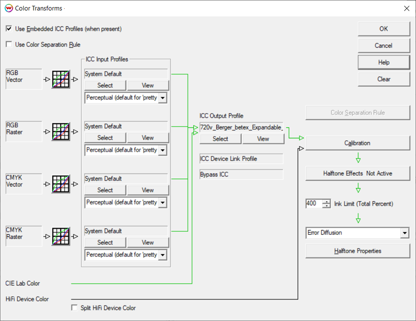
To do this, open the Color Transform window. In the middle section of this window is the ICC Output Profile section. It should still show None as the profile. Browse for the correct ICM or ICC file in the directory where it was saved from the profiling software. Once the output ICC profile is selected, the arrows on the Color Transforms window should turn green, indicating that the color workflow is working correctly with an output ICC profile in place.
Click OK until the Save As window is displayed. Save the Imaging Configuration with the final desired name. We recommend using the Resolution_Inkset_Media naming convention to make it easier to find the Imaging Configuration later. Clicking OK will save the Imaging Configuration. The new Imaging Configuration can now be accessed from the Imaging Configuration pull-down menu on the Print Setup window.
STEP 10: PRINT PROFILE TEST
If you are completing the Wasatch Color Profiling Assessment program you should print a Self Documenting Test File now. This print should be sent to us at the end of the process.
With the new Imaging Configuration complete, we recommend printing a reference file to help determine the quality. Wasatch does not supply a file for this use, but we suggest creating one internally as a final standardized testing procedure. This test file should be one in which the original color is standardized. We recommend NOT using a customer file or a random color file as it will be difficult to locate color issues in these types of files. Rather, Wasatch recommends printing a standard, familiar image that has primary colors, secondary colors, and an image with details like faces with gradients, shadows, etc.. It should also have both CMYK and RGB components.
Be sure that all color and printer settings are consistent with the settings used when the ICC profile was generated. RIP and print the test image.
Analyze the print for quality assurance in order to determine whether the new Imaging Configuration should pass or fail. Things to check include: posterization, bleeding, banding, and any other abnormalities. Also, check the final print for saturation and overall color. Keeping in mind that different substrates (media) will look different, it is reasonable to ask: "Is this the expected behavior for the media and resolution?"
NOTE ON HI-FI PROFILING
Hi-Fi profiling refers to creating Imaging Configurations in SoftRIP using a printer that has an inkset with colors beyond CMYK; such as RGB, OrGr, or RdBl. For these inksets, please refer to the instructions below for important differences in the steps above when creating Imaging Configurations.
As in Step 3, it is important to select the appropriate target file for the densitometer being used. For Hi-Fi profiling, due to the increased number of colors, it is important to select a target file that will include the total number of colors being profiled. To do so, determine the total number of non-dilute colors in the printer's inkset. Here are a few examples:
- CMYKLcLmOrGr and CMYKRdBl : has 6 non-dilute colors
- CMYKLcLmLkLlkRGB : has 7 non-dilute colors
If the inkset includes dilute colors, such as Lc, Lm, Lk, Llk, etc., SoftRIP treats these as supplemental to the color channel they are a dilute of and should not be included in the total count of color channels. For example, the inkset CMYKLcLmLkLlkRGB has eleven different inks but only has seven primary color channels. In this example, the target file generalTest018eyeone_7color.ps would be the correct choice.
Once the total number of non-dilute colors has been determined, use the version of the generalTest018eyeone_Ncolor.ps where 'N' is the number of non-dilute colors in the inkset. Use this target for steps 3 through 7, above, in the same manner as when creating a CMYK Imaging Configuration. Once Step 7 is complete, and the linearization is confirmed, proceed with the steps below.
After printing the generalTest file for the linearization check that is done during the validation in Step 7, scan the linearization target to verify that it is linear and examine the row of composite black patches (running from 25% to 400%) located in the top right corner for any over-inking artifacts.
Use the value of the patch with the most ink that doesn't bleed to set the Total Ink Limit when generating the first target from the ICC profiling software. After the ICC profiling target file has been generated with the Total Ink Limit used from the step above, print the generalTest file and examine it for any over-inking issues. If none exist, proceed to scan this target and generate an output ICC profile, then import into SoftRIP as outlined in Step 8.
If the printed ICC profiling target does have over-inking issues, go back to the ICC profiling software and generate a new target with a larger reduction. If there are only a few places with minor bleeding, it may be best to let the target dry for an hour or so, scan, and see if the ICC profile generated from the data creates a quality result.


